Mig 100 Welder Not Feeding Wire
- #1
I have a Sealey Mighty Mig 130 XT, and the wire feed has stopped working. I was using it yesterday to weld some fairly thick steel, making up some spot light brackets (the wire feed as turned almost all the way up)
Then today not a peep out of it!
Is there anything I can check at home????
Any suggestions would be very welcome!
Gav
- #2
The usual checks.
If the thing is completely dead.
Make sure the power to the machine is good.
Check the fuses in the machine.
And check the switches.
If it has power but won't feed the wire and has no welding current to the torch.
Check the torch switch and wires.
If it has welding current between the torch and ground, but the wire-feed doesn't run.
Unhook the wire-feed motor from the control board and try powering it from a 12v power source.
If the motor runs from 12v, that would probably narrow it down to just the motor speed control on the board.
Robert
- #3
cheers for that! ill have a play tomorrow
- #4
This is why i love this forum! i had the exact same problem with my welder yesterday (same model). and wierdly i did everything that you suggested R Kraft! The trigger is fine (and you can here a relay type noise click in when you press it). The motor spun up fine so i assume it must be speed controller circuit board? Is ther anything i can do to test/fix this or is it just buy a new one? any hemp woul dbe much appreciated, oh and sorry for stealing your thread Kooder!
- #5
The usual failure would be the output transistor.
If you could post a photo of the PCB,maybe someone could suggest a few tests or cheap replacements to try.
Robert
- #6
The usual failure would be the output transistor.
If you could post a photo of the PCB,maybe someone could suggest a few tests or cheap replacements to try.
Robert
Will do! ill get some up tomorrow!
Any luck with yours Kooder??
- #7
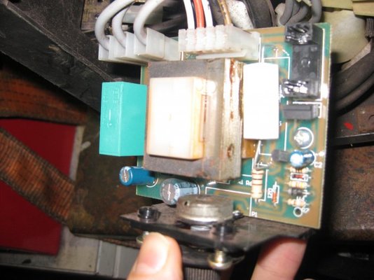
..........eventually got round to taking some snaps. I think this is the culprit, anyone have any ideas if i can test it with a multimeter etc?
-
IMG_0976.jpg
64.7 KB · Views: 1,925
weldequip
Member
- Messages
- 5,306
- Location
- England
- #8
There's a fuse missing from the holder for a start ![]()
- #9
Haha Id taken it out to test  ,.....and its fine
- #10
What are the numbers associated with the black component, just below the fuse holder in the photo.
Robert
- #11
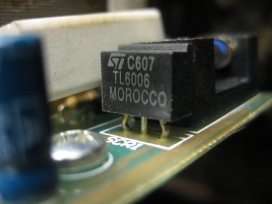
Think these are the numbers you are after......can i ask reason why?
-
IMG_0983.jpg
38.8 KB · Views: 654
-
IMG_0993.jpg
51.5 KB · Views: 669
- #12
Functionally, it seems to, be the same as this circuit.:http://www.mig-welding.co.uk/forum/album.php?albumid=918&pictureid=4389
You would make sure the white rectangular resistor was working, it should have around 4ohms of resistance, or whatever it is marked.
The power from the welding output voltage goes through the fuse,through the resistor and through the SCR1.
The SCR1 it controlled by the small transistor (next to the screw) that measures and regulates the motors voltage.
The pot on the front of the pcb changes the biasing of the transistor and controls the voltage on the motor.
The SCR is normally turned all of the way on.
When the voltage/ back emf get high enough,the transistor shunts the gate drive of the SCR to ground and turns it off.
You could test the SCR circuit by removing the transistor from the board,if the scr circuit is right the motor should run at full speed.
If it does not run at full speed it would be the rectangular resistor,the scr1 or the gate drive resistor.
Robert
- #13
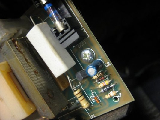
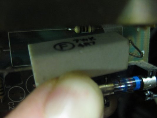
right then, removed the resistor and it seems have a resistance of 5ohms, im not sure what its rated too though, pic below. I then got confused as im unsure what transistor you mean? as the two items near the screw are a capacitor and resistor arent they? ive also found the circuits for the machine, if this helps R kraft. Thanks for your help by the way, if i can sort this out it would make me avery happy chap!
-
IMG_0996.jpg
31.9 KB · Views: 1,294
-

IMG_0997.jpg
49.9 KB · Views: 1,382
![]()
shenion
Tool Pack Rat
- Messages
- 7,586
- Location
- Stone Mountain, GA USA
- #14
See if there is any AC voltage on the output of the transformer on the PCB or at least measure the resistance of primary and secondary.
The resistor is 4.7 ohms (4R7).
- #15
The board basically has two circuits on it.
The 220v power relay that is powered by the 24v PCB transformer and switched by the trigger switch.
And the motor drive circuit, that uses the welding output voltage to run the motor.
The relay on the PCB does click when the trigger is pressed ?.
A transistor of the type on that board looks like this.:http://www.fairchildsemi.com/ds/KS/KSP42.pdf
Robert
- #16
Thanks for getting back so soon, and apologies for not replying, been laid up in bed ill! Anyhow, removed the transistor and the motor still did not spin. The relay does trip in and out when the trigger is pressed so am i correct in saying it would be worth getting another SCR1?
- #17
There should be a resistor and maybe a diode that run the gate,from the PCB's positive power in.
If you have power across the SCR when the trigger is pressed and the gate components are good, that would leave the SCR as the bad component.
As you face the labeled side of the SCR the leads should be Cathode,Anode and Gate.
The Anode is positive power,the Cathode is negative.
The Gate hooks them together, when the Gate is made positive relative to the Cathode,like a closed switch.
I don't know if this makes sense to you, If I explained it poorly I can try again.
Robert
NotANormalCoder
Retired fixer of welders
- Messages
- 315
- Location
- Surbiton - Surrey -UK
- #18
Bear this in mind - These machines use welding voltage to drive the motor, the speed of which is regulated by the transistors as previously described by others. So, no weld volts, no wire speed. Make sure you have output, as it could simply be that the relay feeding the main transformer could be burned out, or quite often, the voltage range switches/connections fail. Quick test, feed wire manually through the torch, touch wire to test metal pull trigger and see if it arcs. If not, there is no weld output, if it does, then it's probably the pcb.
Dave
- #19
Dave, i had a nigling thought in the back of the head that i should do what you said when i first had the problem, mainly due to shenion's post earlier. I did and had no arc, but for some stupid reason i just glossed over it, mainly due to i could still here the relay on the PCB clicking in when i hit the trigger?? Ive just ordered a new PCB at £88 as well, because i was getting annoyed at phaffing around and not having a working welder!
weldequip
Member
- Messages
- 5,306
- Location
- England
- #20
88 quid!  You should of give us a shout, 60 odd & off the shelf!
Hope it does the trick.
Source: https://www.mig-welding.co.uk/forum/threads/help-stopped-feeding-wire.21314/
0 Response to "Mig 100 Welder Not Feeding Wire"
Post a Comment